

tFUS Transducer Manufacturer Essentials: What to Look for in a Reliable Supplier
2026-08-31
If you're sourcing transducers for transcranial focused ultrasound, you already know the margin for error is razor-thin. A supplier's spec sheet can look flawless, yet beam distortion, thermal drift, or inconsistent acoustic output quietly derail entire studies. That's why choosing a manufacturing partner isn't just a procurement checkbox—it's the difference between reproducible results and costly rework. In this guide, we break down the essentials: what to probe in materials, testing protocols, and design flexibility. Along the way, you'll see how Siansonic has built a reputation around addressing these exact failure points, but we won't spoon-feed the answer. You'll finish with a sharper checklist—and maybe a few uncomfortable questions for your current vendor.
Piezoelectric Consistency and the Real Cost of Batch Drift
When a production line drifts, nobody measures the drift itself—they measure the fallout. In piezoelectric ceramics, that fallout shows up as resonant frequency scatter, impedance mismatches, and coupling coefficients that quietly eat away at transducer yield. A batch that leaves the sintering furnace with a 2% variance in d33 might pass incoming inspection, but six months later it becomes a field return, a recalled lot, or a medical device that fails calibration mid-procedure.
The real cost isn't the scrap bin. It's the engineering time spent re-tuning drive circuits to accommodate inconsistent elements, the statistical process control charts that stop telling you anything useful, and the slow corrosion of trust between supplier and OEM. One drifted lot forces you to widen acceptance windows, and once those windows widen, they rarely close again. Consistency is cheaper than correction—but only if you catch the drift before the poling rig does.
Batch drift also punishes downstream automation. A robot that dispenses adhesive based on nominal resonance frequency will misplace beads when the piezo element arrives 200 Hz off target. Yield losses compound silently: 1% here, 3% there, until a profitable line turns marginal. The cure is not more inspection; it is tighter control of raw powder morphology, electrode paste rheology, and poling field uniformity. Those who ignore batch drift pay for it in rework, warranty, and lost customers—long after the original invoice is signed.
Acoustic Characterization Beyond a Single Frequency Sweep
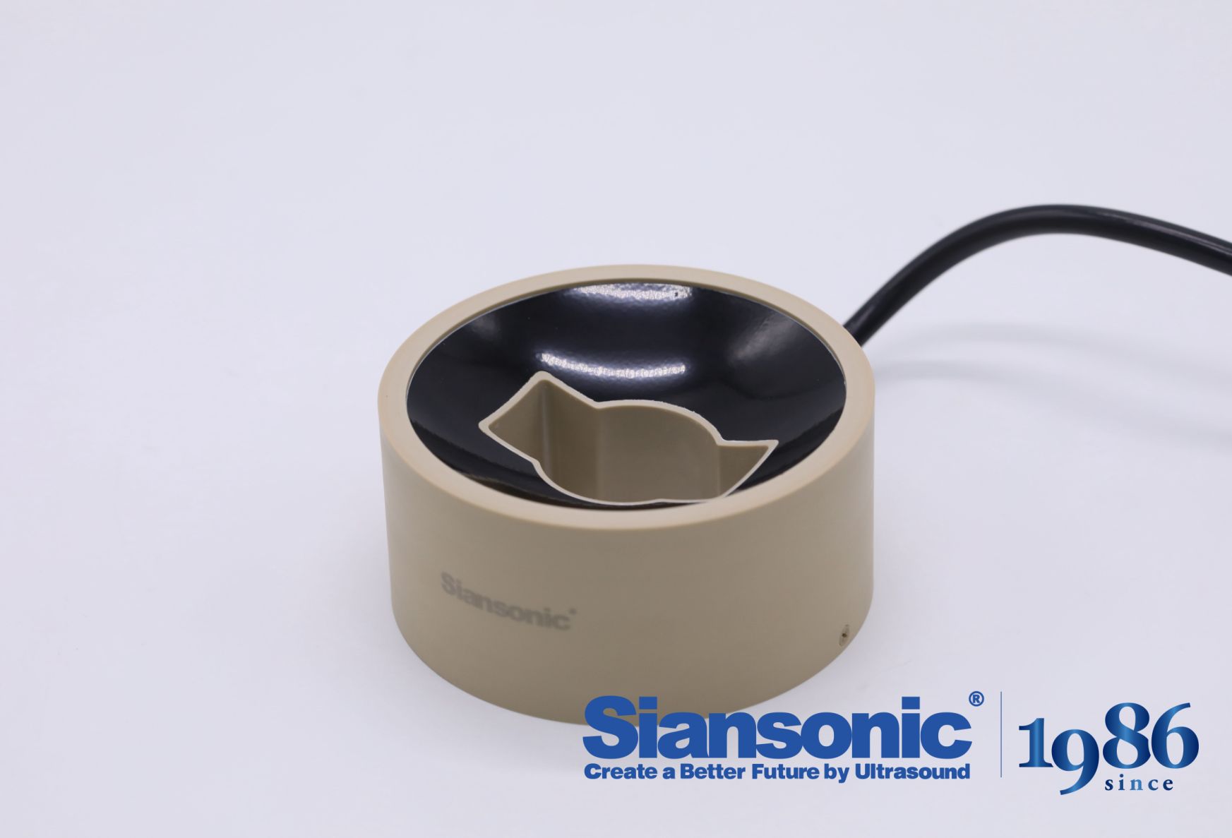
Single frequency sweeps have long served as the default method for mapping resonance and damping, but they tend to flatten behavior into a neat, averaged curve. Real transducers, enclosures, and listening spaces rarely behave that predictably once signal levels, temperature, or mounting conditions shift. Measuring at one level or with a slow logarithmic sweep can hide jump resonances, hysteresis, and even subtle rubs or buzzes that only appear under specific drive conditions.
A more revealing approach combines stepped level tests, multi-tone stimuli, and time-domain captures after the sweep ends. Instead of accepting a single impedance or SPL trace, you look at how the decay envelope changes with drive, whether harmonic structure shifts between small-signal and large-signal operation, and how the driver's suspension memory shows up in the first few cycles. These off-sweep observations often expose issues that a textbook frequency response would call insignificant.
Applying this broader toolkit doesn't require abandoning the sweep entirely. It means treating it as a starting point, then deliberately probing the spaces between the usual measurement points. Short bursts, shaped noise, and repeated stepped sine segments can reveal thermal compression and parameter drift that static curves miss. The result is a characterization that reflects how a device actually behaves in use, not just how it performs on a bench under one carefully controlled excitation.
Custom Focal Depths Without Redesigning the Whole Array
Adjusting focal depth usually means reworking the entire lens stack from scratch, but that's a costly and time-consuming habit. Instead, you can tune individual zones by modifying only the spacer layers or swapping out a single optical element near the sensor. This approach keeps the bulk of the array intact while shifting where the sharpest plane lands, giving you fine control without burning a week on redesign.
What makes this practical is that most arrays have at least one or two elements whose spacing or curvature dominates the depth response. By tweaking those, you can move the focal point forward or back by several millimeters without touching the outer housing or the main grouping. It's a surgical edit rather than a full teardown, which means fewer model updates and less tolerance drift across the production line.
The real payoff comes when you prototype multiple focal configurations side by side. Using the same base array and just swapping a shim or a single lens element lets you test near, mid, and far field performance in parallel. You end up with a family of depth variants that share common parts, so inventory stays simple and design iterations happen in hours, not weeks.
Thermal Behavior Under Continuous Duty Not Just Burst Mode
When a system runs continuously, heat doesn't get a chance to dissipate in short, sharp bursts followed by cool-down periods. Instead, it builds up steadily, reaching a steady-state temperature that can be much higher than the peak temperature during intermittent operation. This is often overlooked by designers who focus on burst ratings.
The thermal time constants of materials come into play differently. In burst mode, the thermal mass of the motor or driver can absorb short spikes without significant temperature rise. Under continuous duty, however, the insulation, bearings, and solder joints experience sustained elevated temperatures, accelerating aging and reducing reliability. You can't rely on the cool-down phase to reset the temperature.
Effective continuous-duty thermal design means sizing heat sinks, airflow, or liquid cooling for the actual average power dissipation, not the peak. It also means understanding that derating curves shift once the duty cycle approaches 100%. Engineers who validate only with short tests often miss failures that appear after hours of steady operation.
Traceability That Survives Regulatory Audits Without Panic
Most teams treat traceability as a document to update right before an audit, which is exactly why panic sets in. The better approach is to let the links between requirements, code, tests, and releases emerge from the tools already in use. When a requirement changes, the related test cases and commits should be tied together automatically, not through someone's memory or a separate spreadsheet that quickly goes stale.
During an audit, the hardest question to answer is usually why a particular requirement never got updated. A lightweight traceability view helps here: each requirement sits next to its design notes, code review threads, test results, and release tags. You don't need perfectly formatted matrices. You need a living record that's easy to scan. Embedding requirement IDs in branch names and commit messages turns your version history into an audit trail that auditors can follow without asking you to explain every gap.
When an auditor challenges a trace, the best response is to point to existing evidence rather than improvise a story. Spending ten minutes every couple of weeks checking for missing links prevents the late-night scramble before a regulatory review. Traceability that survives audits isn't built from heroic last-minute effort; it's a byproduct of small, consistent habits that keep the chain intact.
Post-Delivery Tuning Support When the Target Moves
Once a model is in production, the assumptions that held during development rarely stay fixed. Customer behavior shifts, market conditions evolve, and the very definition of what you are predicting can change. Post-delivery tuning support addresses this reality by monitoring drift in both input data and target outcomes, then adjusting thresholds, retraining on fresh examples, or redefining success metrics without requiring a full rebuild.
Rather than treating deployment as the finish line, this support layer establishes a feedback loop where predictions are compared against actual results over time. When the target moves—say, a fraud pattern mutates or a recommendation becomes less relevant—the system flags the divergence and the tuning process kicks in. This might involve reweighting recent samples, introducing human-in-the-loop corrections, or patching feature pipelines that no longer reflect the current environment.
The practical value lies in speed and continuity. Teams avoid the costly cycle of tearing down and rebuilding models from scratch. Instead, small, targeted adjustments keep performance within acceptable bounds until a more substantial redesign is warranted. This ongoing partnership between the delivery team and the operating environment turns model maintenance from a reactive firefight into a managed, evolving service.
FAQ
Look beyond the generic ISO 9001. A supplier serious about medical-grade focused ultrasound will have ISO 13485 as a baseline, and if you're targeting clinical or regulatory pathways, expect IEC 60601-2-62 compliance for therapeutic ultrasound equipment and documentation support for FDA 510(k) or CE marking. Ask for their device history records and cleanroom assembly proof, not just a certificate on a wall.
Ask the supplier for full characterization reports: impedance plots, beam profiles, focal spot dimensions, and acoustic power output across the operating frequency range. A dependable manufacturer will offer third-party acoustic measurement data or invite you to witness testing. Watch out for suppliers who only provide a single center-frequency number—real tFUS performance lives in the harmonics and side-lobe control.
It's the difference between a transducer that drifts after 50 hours and one that holds steady for 500. PZT-8 and hard PZT variants handle high drive levels with less heat, while single-crystal PMN-PT offers broader bandwidth if your protocol demands multi-frequency pulsing. Ask about aging rates, depolarization thresholds, and whether they match backing and matching layers to the specific ceramic rather than using a one-size-fits-all stack.
Yes, but not every manufacturer has the in-house acoustic simulation and precision machining to do it well. Request examples of past non-circular aperture designs, phased-array segmentation, or concave focusing with tight radius tolerances. A capable partner will run FEA simulations before cutting material and share the predicted vs. measured field difference, not just promise custom shapes.
Look for batch-level consistency testing: impedance magnitude and phase, capacitance, insertion loss, and focal pressure mapping on every unit—not just a final electrical go/no-go test. Also probe their defect tracking: how do they handle a transducer that fails acoustic output after encapsulation? If they can't explain their rework criteria or traceability from ceramic lot to finished device, walk away.
Critical, because transcranial focused ultrasound often runs at high duty cycles. A reliable supplier will discuss active cooling channels, thermally conductive backing materials, or pulse-sequence limitations openly. If they claim a transducer can run continuous-wave at maximum rated power without temperature rise data, treat it as a red flag. Ask for thermal imaging or thermocouple test results at different drive levels.
At minimum, a clear warranty covering acoustic output degradation, not just physical damage, and a recalibration or repair service. The best suppliers will offer failure analysis reports, loaner units during repairs, and guidance on drive electronics matching. If their support ends at shipment and they don't ask about your amplifier impedance or cable length, they're not invested in your transducer's real-world performance.
Don't buy on price per unit alone. A low-cost transducer that loses 15% acoustic power after three months costs more in repeated replacements and experimental inconsistencies than a 30% pricier unit with a 2-year performance warranty. Ask for lifetime test data or references from labs running similar protocols. If a supplier can't provide any longevity evidence, assume you're paying for a disposable prototype, not a reliable instrument.
Conclusion
Choosing a tFUS transducer supplier means looking past glossy datasheets. Piezoelectric consistency is where many projects quietly unravel—batch-to-batch drift can shift acoustic output enough to invalidate weeks of in vivo work. A reliable manufacturer will show you per-lot impedance and capacitance data, not just a single golden sample. They should also go beyond a basic frequency sweep. Ask for full acoustic field mapping, pressure distribution across the aperture, and harmonic distortion figures under realistic drive levels. This kind of characterization reveals dead spots and side lobes that a narrow sweep misses. Equally important is flexibility in focal depth. You should not need to pay for a full array redesign every time a study shifts from rodent to larger animal models. Look for suppliers who can adjust lens geometry, element spacing, or phasing patterns without rebuilding the entire transducer stack.
Thermal behavior is another differentiator. Many transducers perform fine in burst mode but degrade under continuous or high-duty-cycle protocols. A trustworthy manufacturer will provide thermal imaging or embedded thermocouple data at the duty cycles you actually plan to use. Regulatory readiness should not feel like a last-minute scramble. Demand traceability that includes raw material certificates, assembly logs, and test reports tied to each serial number—so when an auditor asks for evidence, you can retrieve it without panic. Finally, post-delivery support matters more than most teams expect. Research targets move: a new brain region, a different skull thickness, a revised safety margin. The supplier should offer tuning support—whether that means on-site recalibration, remote diagnostics, or advice on re-matching the impedance network—without requiring you to purchase a new transducer. These practical checks separate commodity vendors from genuine partners in focused ultrasound development.
Contact Us
Contact Person: Ivy Zhang
Email: [email protected]
Tel/WhatsApp: +86 1081502288
Website: https://www.siansonic.com/