

Best Character LCD Display Modules for Embedded Systems and DIY Projects
2026-11-16
Nothing derails an embedded project faster than a display that's dim, flaky, or a pain to wire up. Whether you're debugging a prototype or adding a readable status screen to a DIY gadget, the right character LCD module saves hours of guesswork. After testing dozens of panels, Jingda-Display keeps coming up as a reliable source for crisp, affordable 16x2 and 20x4 displays that actually survive real-world tinkering. In this guide, I'll break down the options that earn their place on your workbench—from sunlight-readable screens to interfaces that won't fight your microcontroller.
Choosing Between Parallel and I2C Without Overcomplicating the Wiring
When your project starts filling up with sensors and displays, the wiring can quickly turn into a tangled mess if you pick the wrong communication method. Parallel connections are straightforward and fast, but each signal needs its own wire, so a simple 8-bit display suddenly demands eight data lines plus control pins. I2C, on the other hand, bundles everything onto two wires, which keeps the physical layout clean even as you add more devices. The trade-off is speed and a bit more protocol overhead, but for most hobbyist setups that rarely matters.
A practical way to decide is to count how many pins you actually have free on your microcontroller. If you're already running low and still need to hook up a real-time clock, an EEPROM, and a small OLED, forcing a parallel interface means adding shift registers or port expanders, which defeats the purpose. I2C shines here because you can daisy-chain multiple devices with different addresses on the same two wires, and the hardware handles the addressing for you. Reserve parallel wiring for cases where you need to push lots of data fast, like driving a TFT screen at high refresh rates, or when you're stuck with a legacy component that only speaks parallel.
Don't overengineer the choice. Start with the physical reality of your breadboard or PCB: if you can route eight or sixteen traces without crossing over a dozen other wires and you value maximum throughput, parallel is fine. If you'd rather keep the wiring simple and accept slightly slower updates, I2C will save you hours of debugging. Many beginners overthink bus capacitance and clock stretching, but at typical distances of a few inches with standard pull-up resistors, those are non-issues. Pick the option that leaves your wiring neat enough to troubleshoot later.
Setting Contrast and Backlight So Text Stays Sharp in Any Light
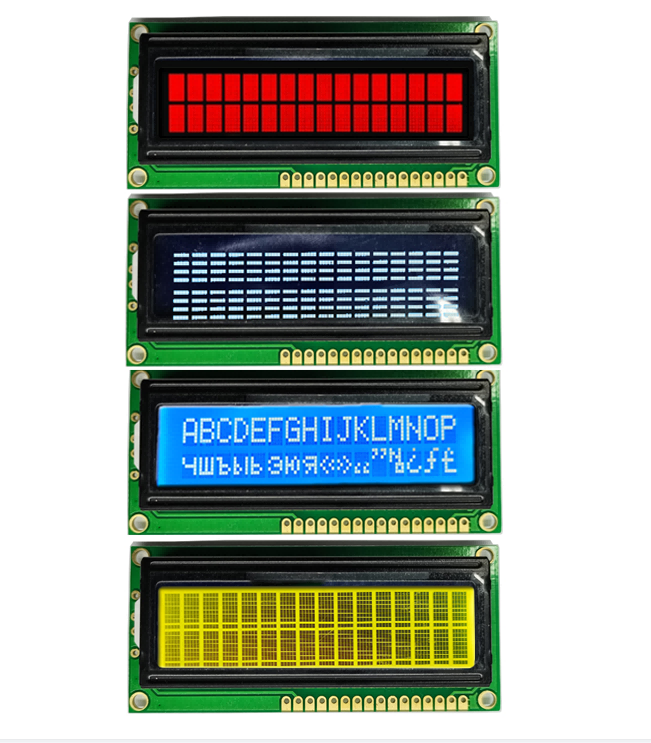
A screen that looks perfect indoors can become unreadable the moment you step outside. The key is to stop relying on a single brightness level and instead pair a strong backlight with a carefully tuned contrast ratio. When the backlight is too low, dark text on a light background turns muddy; when contrast is too aggressive, bright areas blow out and fine details disappear. The goal is a balanced setting that preserves edge definition without forcing your eyes to work harder.
Start by raising the backlight only as much as the ambient light demands. In direct sunlight, push it high enough to overcome glare, but avoid maxing it out indoors, where a lower backlight reduces eye strain and saves power. Then adjust contrast until the thinnest strokes in letters and UI elements stay crisp. A useful test is to look at a small lowercase “e” or a thin divider line: if the hole in the “e” fills in or the line fades into the background, contrast needs a nudge.
For displays with automatic brightness, don’t simply trust the default curve. Many auto modes react too slowly or overcorrect in mixed lighting, so set a manual baseline first and let the sensor make only small adjustments. In dim rooms, reduce backlight and slightly lower contrast to avoid halos around bright text. In bright environments, increase both but watch for color shift—especially on OLED panels, where high brightness can make saturated colors bleed. The right combination keeps text sharp and readable without washing out the screen.
Creating Custom Glyphs Without Eating Up All the Memory
A common mistake when building a text rendering engine is to pre-render every possible character into its own texture. That approach balloons memory usage fast, especially with large Unicode ranges. Instead, use a dynamic glyph atlas: a fixed-size texture (say 1024x1024) where only the characters your app actually needs get rasterized on demand. When the atlas fills up, evict the least recently used glyphs and pack new ones into the freed space. This keeps memory bounded and predictable regardless of how many different characters a user might encounter.
For projects that need crisp scaling without huge textures, signed distance fields are worth the extra implementation effort. You store a small grayscale image per glyph where each pixel encodes the distance to the nearest edge. At runtime, a shader can reconstruct sharp outlines at any size, so you never need to bake multiple font sizes. A single 64x64 distance field per glyph often looks better than a 256x256 traditional bitmap, and you can pack hundreds of them into one modest atlas.
Another overlooked trick is font subsetting. Most font files contain thousands of glyphs you will never draw. Strip the unused outlines and kerning tables before loading, keeping only the characters your interface actually references. Pair that with a compact binary format for glyph outlines—like raw quadratic bezier points instead of parsed font objects—and you can cut memory usage by an order of magnitude. When a rare glyph does appear, fall back to path rendering on the CPU rather than expanding the atlas.
Quieting Noise and Crosstalk That Cause Random Characters
Random characters appearing in a data stream often trace back to electrical noise and crosstalk, not software bugs. A logic receiver decides between high and low based on a voltage threshold; when coupled energy from an adjacent trace or external interference pushes the signal across that threshold at the wrong moment, the receiver samples a bit that was never transmitted. This is especially common with single-ended parallel buses or long ribbon cables where every transition on one wire can inject a small current into its neighbors.
Crosstalk has two distinct flavors: near-end and far-end, each influenced by trace separation, edge rate, and termination. Fast rise times aggravate the problem because the coupled pulse amplitude scales with the rate of change of voltage. Meanwhile, power supply ripple and ground bounce can shift the reference level of an entire chip, making otherwise clean signals appear noisy. In asynchronous serial links, a single corrupted start bit can throw off the entire frame, producing a garbage character even if all subsequent bits are perfect.
The most effective fixes are physical: increase spacing between conductors, route sensitive signals away from high-speed switching nodes, use differential pairs like RS-485 to reject common-mode noise, or add series resistors to slow down edges that cause coupling. Bulk decoupling capacitors and a solid ground plane reduce power rail fluctuations that masquerade as signal noise. These measures quiet the channel before the data ever reaches the decoder, so random characters stop appearing at the source.
Mounting the Display So It Survives Heat, Vibration, and Curious Hands
Getting a display to last in a tough environment starts with the mounting hardware, not the screen itself. Use steel brackets with vibration-damping grommets at all four corners instead of rigid plastic clips. The grommets absorb low-frequency rumble from nearby motors or foot traffic, while the metal frame keeps the panel from flexing. Leave at least a 15 mm air gap behind the display for passive airflow, especially if the wall or enclosure radiates heat. For outdoor or factory settings, choose a mount with a built-in heat shield that deflects direct sunlight away from the rear electronics.
Small hands and stray tools are just as dangerous as thermal cycling. Position the display so the screen sits slightly recessed behind a bezel or protective lip, which prevents casual finger pokes and accidental impacts from carts or boxes. If you can't recess it, add a clear polycarbonate cover with an anti-glare coating—this keeps the touch surface usable while taking the brunt of scratches and smudges. Mount the display at a height that puts the center of the screen at least 1.2 meters off the ground, which is high enough to deter most toddlers but still comfortable for adult interaction.
Finally, route all cables through a strain-relief channel inside the mount, not dangling loose behind the panel. A cable that hangs freely will act like a lever during vibration, slowly loosening connectors or cracking solder joints. Use right-angle connectors and zip-tie the bundle to the back plate every 10 centimeters. For areas with wide temperature swings, add a small thermostatically controlled fan that only kicks in above 45°C—this avoids constant dust intake while still venting heat when the display is working hard. Test the whole assembly by running it at full brightness for six hours, then gently push on each corner of the frame. If you see any backlight bleed or image distortion, tighten the grommets or add a cross brace before putting it into service.
Reusing One Code Base Across Arduino, ESP32, and Raspberry Pi
Maintaining separate firmware for every board you own quickly turns into a mess. A shared code base lets you handle hardware differences in one place instead of scattering board-specific checks across dozens of files. Start by isolating pin mappings, timing functions, and communication interfaces behind a thin abstraction layer. Then each target board gets its own configuration header, while the core logic stays identical.
The real trick is accepting that not every feature will exist on every platform. Wi-Fi code makes sense on an ESP32 or a Pi, but not on a bare Arduino Uno. Use conditional compilation sparingly and lean on runtime capability checks where possible. In practice, most projects only need a handful of variations: a different I2C address here, a faster SPI clock there. Collect those differences in a board profile struct and pass it into the shared code at startup.
Testing across three architectures sounds heavy, but a simple build script can compile the same source files against each toolchain. When you fix a bug in the sensor parsing routine, that fix automatically applies to all boards. Over time, this approach saves far more effort than juggling three separate codebases—and it keeps the project maintainable long after you have forgotten which board was wired to which pin.
FAQ
They are simple to drive, need very little processing power, and remain readable even in bright sunlight—unlike many graphical or OLED alternatives. For a status display on an industrial controller or a basic sensor readout on a workbench, a 16x2 or 20x4 character LCD is often the most reliable choice.
Look for I2C or SPI backpacks if you want to save GPIO pins and keep wiring minimal. A standard parallel HD44780 module is fine when pin count doesn't matter, but adding an I2C adapter makes it much easier to chain multiple displays or fit everything into a small enclosure.
Many newer character LCD modules are designed for 3.3V logic, but older HD44780 clones often expect 5V. Check the datasheet for the logic high threshold. If you only have a 3.3V board, either buy a module with a built-in level shifter or use a separate 5V supply and a bidirectional level converter for the data lines.
Forgetting to connect the contrast pin (V0) properly. Without a contrast trimmer or a resistor to ground, the screen can look completely blank or show only faint squares. A 10k potentiometer between VCC and GND with the wiper to V0 is the simplest way to adjust it.
Yes, transflective or reflective modules with no backlight are better for direct sunlight. For shade or indoor use, a high-contrast negative display with an RGB backlight gives you more color options, but pure sunlight readability usually means turning the backlight off and relying on ambient light.
For Arduino, the LiquidCrystal library works fine for parallel modules, while LiquidCrystal_I2C handles the common PCF8574 backpack. On ESP32 with ESP-IDF, you can use the built-in HD44780 driver or the community 'lcd' component. For MicroPython, the 'lcd_api' and 'i2c_lcd' modules are a good starting point.
The biggest issue is usually the I2C address—many backpacks default to 0x27 but some are 0x3F, and address collisions happen if you add other sensors. Also, the backpack's contrast pot may need adjusting after soldering. If the display only shows the first line or garbled text, check that the backpack is seated correctly and that you wired SDA and SCL to the right pins.
It is possible but not ideal. The backlight is the main power draw, often 20-50 mA, while the controller itself uses under 2 mA. If you need occasional readouts, add a push button to toggle the backlight on for a few seconds. For continuous battery operation, consider an e-paper display instead, but a character LCD can work if you accept shorter battery life or use a larger LiPo cell.
Conclusion
Character LCD modules remain a staple in embedded systems and DIY builds because they are readable, cheap, and easy to drive. The first real decision is between parallel and I2C. Parallel gives you speed but eats up eight or more GPIO pins, while I2C keeps wiring to just two data lines plus power. For most hobby projects, I2C is the practical choice—just watch out for address collisions and weak pull-ups. Once you have the display talking, take the time to set the contrast potentiometer properly. A few degrees of rotation can mean the difference between crisp text and faint blocks. Backlight current should be limited with a resistor or PWM so it does not wash out the characters in dim rooms or glare in bright light. Random characters that appear out of nowhere are almost always a wiring or power issue, not a faulty module. Twisted or short data lines, a solid common ground, and a 0.1 µF capacitor across the supply pins will eliminate most crosstalk and noise. If you need custom glyphs, use the CGRAM slots sparingly. Design your own 5×8 patterns and load only the icons you actually need, reusing them across different screens instead of filling every slot.
Mounting matters more than people expect, especially in hot or vibrating environments. Leave a small air gap behind the PCB, use nylon standoffs, and avoid overtightening screws that can flex the glass. For anything within reach of curious hands, a simple bezel or acrylic cover keeps the display from being poked or scratched. When it comes to code, do not rewrite everything for each board. Build a thin hardware abstraction layer with functions like lcd_init(), lcd_write(), and lcd_set_cursor(). Then the only changes between an Arduino, ESP32, or Raspberry Pi are the low-level I2C or GPIO calls—Wire.h on Arduino, the ESP32’s native I2C driver, and lgpio or smbus on the Pi. Keep pin assignments in a single config header, and your whole project becomes portable in minutes. This approach saves time and makes it easy to swap displays or microcontrollers when a prototype turns into a permanent installation.
Contact Us
Contact Person: Vincent
Email: [email protected]
Tel/WhatsApp: 86 135 5485 1379
Website: https://www.jda-display.com/